Products › Torque Sensors › Rotary Torque Sensor
Rotary Torque Sensor
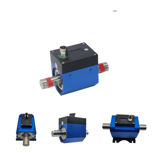
A rotary torque sensor measures torque on a turning shaft and runs in line between a drive and its load. This non-contact series transfers signal and power without slip rings or brushes, so it has no wearing parts, runs at high speed, and outputs torque, speed and power together.
- Models: WTQ-1050 / WTQ-1060 series
- Range: 2 N·m to 2 kN·m (lineup 0.1 N·m to 10 kN·m)
- Speed: up to 15,000 rpm (model dependent)
- Signal transfer: non-contact, no slip rings or brushes
- Outputs: 10±5 kHz, 4-20 mA, ±5/±10 VDC, RS485/RS232
- Accuracy: ±0.1 to ±0.2% FS
- Display: OLED torque / speed / power (optional)
Overview
Torque is the twisting force a motor, engine or actuator delivers to a shaft. A rotary torque sensor sits in that shaft line and reports the live torque, so test engineers can verify output, efficiency and peak loads on running machinery. Because the shaft turns, the measuring element rotates with it and the signal must leave the spinning shaft without a wired connection.
This series does that without slip rings or carbon brushes. A strain-gauge bridge bonded to a calibrated shaft section senses the twist, and a rotary transformer transfers both the excitation power in and the signal out across an air gap. With no contacts to wear, the sensor runs continuously at high speed, needs no warm-up beyond a few minutes, and holds zero without repeated adjustment. If your measurement is on a stationary flange rather than a spinning shaft, use a reaction torque sensor instead.
Features
What sets this rotary torque sensor apart on the test bench:
Non-contact signal transfer
No slip rings or brushes. A rotary transformer couples power and signal across an air gap, so there are no wearing parts and almost no maintenance.
Torque, speed and power
A built-in pickup adds shaft speed, and an optional OLED panel shows torque, speed and mechanical power together.
High-speed capable
Runs up to 15,000 rpm depending on model, suited to motor, engine and dynamometer test benches.
Wide measuring range
One series spans 0.1 N·m micro torque to 10 kN·m, measured continuously in both forward and reverse directions.
Multiple outputs
10±5 kHz frequency, 4-20 mA, ±5/±10 VDC and RS485/RS232 connect to any data acquisition system.
Stable and accurate
Accuracy of ±0.1 to ±0.2% FS with low temperature drift and no need for repeated zeroing.
Working principle
A strain-gauge bridge is bonded to a calibrated section of the shaft. When the shaft carries torque, that section twists by a small angle and the gauges change resistance in proportion to the load. The bridge output is the torque reading.
Because the rotary transformer couples power and signal across an air gap, nothing rubs and nothing wears. The sensor reaches working state a few minutes after power-up, measures continuously in both directions, and holds its zero without repeated adjustment, which is what makes it suited to long, high-speed test runs.
Technical specifications
| Parameter | Specification |
|---|---|
| Measuring principle | Strain-gauge bridge on a rotating shaft, non-contact transfer |
| Measuring range | 2 N·m to 2 kN·m |
| Accuracy | ±0.1 / ±0.2% FS |
| Direction | Bidirectional (forward and reverse) |
| Maximum speed | Up to 15,000 rpm (model dependent) |
| Speed and power | Optional speed pickup; OLED torque / speed / power display |
| Output signals | 10±5 kHz, 4-20 mA, ±5 / ±10 VDC, RS485 / RS232 |
| Supply voltage | 12-30 VDC |
| Zero temperature effect | ±0.02% RO/°C |
| Span temperature effect | ±0.02% RO/°C |
| Compensated temperature | -10 to +60 °C |
| Operating temperature | -20 to +80 °C |
| Shaft material | Stainless steel |
| Electrical connection | 6-pin or 8-pin connector |
| Warm-up | About 5 minutes |
Exact ranges, shaft and flange dimensions and connector options are set per model and order.
Models and ranges
The series runs from micro torque to several hundred kilonewton-metres. Pick by torque range and speed; tell us the shaft and we match the build.
| Model | Type | Torque range | Max speed | Notes |
|---|---|---|---|---|
| Micro series | Non-contact | 0.1 to 10 N·m | High | Smallest ranges, tight spaces |
| 5069 | Non-contact | 5 to 5,000 N·m | 15,000 rpm | OLED torque / speed / power |
| 803 | Non-contact | Up to 100 kN·m | High speed | Short axial length, large shafts |
| 901 | Inline contactless | 2 N·m to 2 kN·m | High speed | Any mounting orientation |
| 1010 / 1055 | Contact (slip ring) | 5 to 1,000 N·m | 1,800 rpm | Lower-cost alternative |
Rotary vs reaction
The first choice is whether the torque is on a turning shaft or on a stationary flange. The two are different instruments.
| Rotary torque sensor | Reaction torque sensor | |
|---|---|---|
| Shaft | Turns in line with the load | Stationary, bolted to the frame |
| Measures | Dynamic torque on a spinning shaft | Static / reaction torque |
| Speed | Up to 15,000 rpm | 0 rpm |
| Typical use | Motor and engine dyno, gearbox, pump | Torque-wrench calibration, screwdriver QC |
| Choose when | The shaft rotates (this page) | The measurement is on a fixed flange (see reaction torque sensors) |
Applications
A rotary torque sensor belongs anywhere torque has to be read on a turning shaft:
- Engine and electric-motor dynamometers
- Gearbox and transmission quality testing
- Power-tool, screwdriver and torque-wrench audit
- Pump, compressor and mixer drive monitoring
- Wind-turbine and generator test rigs
- End-of-line production and R&D test benches
Challenge: A test lab needed dynamic torque on a drive spinning at 5,000 rpm, with the data logged to a PC for analysis.
Solution: A non-contact rotary torque sensor rated for 50 N·m at 5,000 rpm, paired with software for live torque, speed and power.
Result: Torque and speed were captured at full running speed with no slip rings, so the test ran without interruption and the readings fed straight into the analysis software.
Related products
FAQ
How does a rotary torque sensor work?
A strain-gauge bridge is bonded to a calibrated section of the rotating shaft. As the shaft carries torque, that section twists by a tiny angle and the gauges change resistance in proportion to the load. On a non-contact sensor a rotary transformer carries excitation power onto the shaft and the measurement signal back off across an air gap, so the rotating element never touches the housing.
What is a non-contact rotary torque sensor?
It is a rotary torque sensor that transfers signal and power without slip rings or carbon brushes. Inductive coupling across an air gap replaces the wearing contacts, which removes brush noise and maintenance, allows continuous high-speed running, and gives a longer service life than slip-ring designs.
How accurate is a rotary torque sensor?
This series is accurate to about +/-0.1 to +/-0.2 percent of full scale, with low temperature drift and good repeatability. Accuracy depends on the range you choose and on correct alignment, so size the sensor near your working torque rather than far above it.
What is the difference between a rotary and a reaction torque sensor?
A rotary sensor sits in the shaft line and measures torque while the shaft spins, up to thousands of rpm. A reaction sensor is bolted between a stationary frame and the device under test and measures the torque the casing reacts against at zero rpm. Choose rotary for running machinery and reaction for torque-wrench calibration or bench tests.
Can a rotary torque sensor measure speed and power?
Yes. With the optional speed pickup the sensor outputs shaft rotation along with torque, and an OLED panel can show torque, speed and mechanical power at once. The same data is available on the 4-20 mA, voltage, frequency and RS485/RS232 outputs.
Request a quote
Tell us the torque range, the shaft speed and how you mount the sensor, and we configure one rotary torque sensor for your test, not a shelf part. Send the details and our engineers reply with a specification and quote.