Products › Torque Sensors › Reaction Torque Sensor
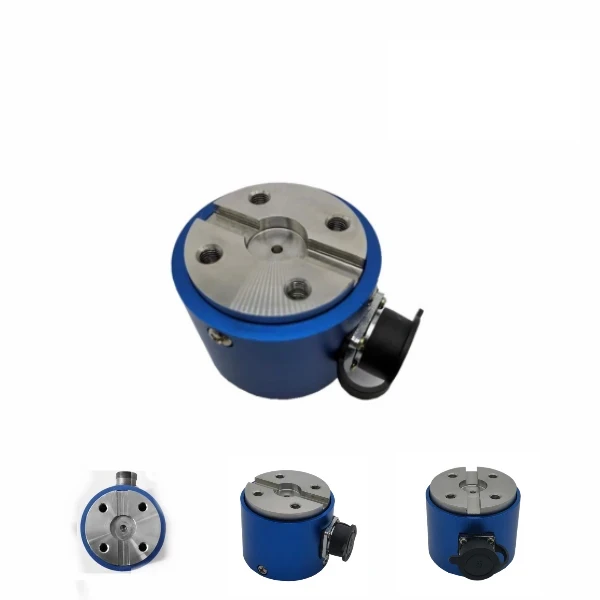
Reaction Torque Sensor
A reaction torque sensor measures torque on a stationary flange. It is bolted between a fixed frame and the device under test and reads the torque the casing reacts against, with no rotation and no slip rings. It suits torque-wrench calibration, motor and fastener bench tests, and any static torque check.
- Range: 0.1 N·m to 5,000 N·m (lineup to 50 kN·m)
- Type: reaction / static, 0 rpm
- Mounting: flange-to-flange, keyed shaft or square drive
- Accuracy: ±0.1 to ±0.3% FS
- Output: 1.5 mV/V bridge; 4-20 mA or 0-5/10 VDC optional
- Build: stainless steel or aluminum, overload protected
Overview
Torque is the twisting force a motor, actuator or fastener delivers. A reaction torque sensor does not turn with the shaft: it is fixed in place, bolted between a stationary frame and the device under test, and it senses the reaction torque the housing tries to twist against. Because nothing rotates, the signal leaves the sensor on a plain cable, with no slip rings or non-contact coupling.
That makes the reaction design simple, stiff and very repeatable, which is why it is the standard choice for torque-wrench calibration, motor and gear-motor bench tests, and fastener studies. If your torque is on a continuously spinning shaft instead, use a rotary torque sensor.
Features
What sets this reaction torque sensor apart on the bench:
Static reaction measurement
Bolts to a fixed frame and reads torque at zero rpm, with no rotating parts and no slip rings to wear.
Multiple mounting styles
Flange-to-flange, keyed shaft, internal or external square drive, plus thin hollow builds for tight spaces.
Overload protection
Mechanical stops protect the element, so an over-torque event does not destroy the sensor.
Wide measuring range
From 0.1 N·m micro torque to 5,000 N·m, measured in both forward and reverse directions.
High stiffness, low deflection
A stiff strain-gauge element gives stable, repeatable readings, which is what calibration work needs.
Stable and accurate
Accuracy of ±0.1 to ±0.3% FS with ≤±0.05% repeatability and low temperature drift.
Working principle
A foil strain-gauge bridge is bonded to the sensing element between the two mounting faces. When the device under test applies torque, the fixed housing reacts against it and the element takes a small, precise strain. The bridge turns that strain into an output proportional to the reaction torque.
Because the element is stiff and never rotates, there is nothing to wear and very little deflection under load. The sensor holds calibration over long runs, which is what makes the reaction design the reference choice for torque-wrench and motor calibration.
Technical specifications
| Parameter | Specification |
|---|---|
| Measuring principle | Foil strain-gauge bridge, reaction (static) torque |
| Measuring range | 0-30 to 150 N·m (series 0.1 N·m to 5,000 N·m) |
| Non-linearity | ±0.1 / ±0.3% FS |
| Sensitivity | 1.5 ±10% mV/V |
| Repeatability | ≤±0.05% FS |
| Hysteresis | ≤±0.05% FS |
| Zero output | ±1% FS |
| Creep | ≤±0.03% FS / 30 min |
| Temperature drift | 0.03% FS / 10 °C (zero and sensitivity) |
| Bridge resistance | 350 / 750 ohm |
| Direction | Bidirectional (forward and reverse) |
| Speed | 0 rpm (stationary) |
| Connection | Keyed shaft, flange-to-flange or square drive (model dependent) |
| Overload protection | Mechanical |
| Material | Stainless steel or aluminum alloy |
| Output | mV/V bridge; amplified 4-20 mA or 0-5/10 VDC optional |
Exact ranges, connection style and dimensions are set per model and order.
Models and ranges
The series covers micro torque to several thousand newton-metres, in flange, keyed-shaft and square-drive styles. Pick by torque range and how you need to mount it.
| Model | Connection | Torque range | Notes |
|---|---|---|---|
| 56 Micro | Flange, both ends | 0.1 to 20 N·m | Smallest ranges, tight spaces, OEM |
| 120 | Keyed shaft, both ends | 30 to 150 N·m | Torque-wrench, motor and engine bench |
| 8050 Thin hollow | Flange-to-flange, hollow | 50 to 1,000 N·m | Disc, drilling and robot-arm joints |
| 2150 Dual range | Keyed flange + flange | 20 to 5,000 N·m | Large and small range in one unit |
| 32 / 22 Square key | Square drive + flange | Per model | Square-drive fixtures and wrenches |
Reaction vs rotary
The first choice is whether the torque is on a stationary flange or a turning shaft. The two are different instruments.
| Reaction torque sensor | Rotary torque sensor | |
|---|---|---|
| Shaft | Stationary, bolted to the frame | Turns in line with the load |
| Measures | Static / reaction torque | Dynamic torque on a spinning shaft |
| Speed | 0 rpm | Up to 15,000 rpm |
| Typical use | Torque-wrench calibration, bench QC | Motor and engine dyno, gearbox |
| Choose when | The element does not rotate (this page) | The shaft rotates (see rotary torque sensors) |
Applications
A reaction torque sensor belongs wherever torque is checked without a continuously spinning shaft:
- Torque-wrench and screwdriver calibration
- Electric-motor and gear-motor bench testing
- Fastener and bolt tightening studies
- Engine, brake and actuator static torque
- Robotics and drilling-head joint torque
- Laboratory and production torque-calibration rigs
Challenge: A test rig had to hold and measure a static, non-rotating torque up to 5,000 N·m, with a voltage output for the rig data system.
Solution: A dual-flange reaction torque sensor rated for 5,000 N·m with a ±10 V output, fixed flange-to-flange between the frame and the load.
Result: The reaction mount measured torque with no rotating parts, and the ±10 V signal connected directly to the rig.
Related products
FAQ
How does a reaction torque sensor work?
The sensor is bolted between a fixed frame and the device under test. A foil strain-gauge bridge on the sensing element takes a small strain as the housing reacts against the applied torque, and that strain becomes an output proportional to the torque. Nothing rotates, so the signal leaves on a plain cable at zero rpm.
What is the difference between a reaction and a rotary torque sensor?
A reaction sensor is stationary and measures static or reaction torque at 0 rpm. A rotary sensor sits in the shaft line and measures dynamic torque while the shaft spins, up to thousands of rpm. Use reaction for calibration and bench tests, and rotary for running machinery.
Where are reaction torque sensors used?
They are the standard tool for torque-wrench and screwdriver calibration, electric-motor and gear-motor bench testing, fastener and bolt studies, and static torque checks on engines, brakes and actuators.
How accurate is a reaction torque sensor?
This series is accurate to about +/-0.1 to +/-0.3 percent of full scale, with repeatability of +/-0.05 percent or better and low temperature drift. The stiff, low-deflection element is what makes it suitable for calibration work.
What mounting options does a reaction torque sensor have?
Common styles are flange-to-flange, keyed shaft, internal or external square drive, and thin hollow builds for tight spaces. Most models include mechanical overload protection. Tell us the fixture and we match the connection.
Request a quote
Tell us the torque range, the mounting style and the test, and we configure one reaction torque sensor for your bench, not a shelf part. Send the details and our engineers reply with a specification and quote.